Precision in Every Tooth: Choosing Between Worm Gear Hobs and Gear Milling Cutters
In modern manufacturing, precision is rarely the result of one big decision. More often, it comes from a series of small, carefully considered choices: the right material, the correct machine setup, a well-planned production process, and perhaps most importantly the right cutting tool.
For manufacturers across the United States, gear production presents a unique challenge. Components must meet demanding dimensional requirements while delivering dependable performance in applications ranging from industrial machinery to automotive systems and power transmission equipment. When gear teeth are not cut accurately, the consequences can include excessive noise, uneven wear, vibration, and costly production delays.
Two tools that play important roles in gear manufacturing are worm gear hobs and gear milling cutters. Although both are used to create gear tooth profiles, they work differently and serve different production needs.
Understanding these differences helps manufacturers make informed tooling decisions, improve machining efficiency, and maintain consistent quality throughout production.
Why Gear-Cutting Tool Selection Matters
A gear is only as reliable as the accuracy of its teeth. Tooth geometry influences how gears engage, distribute loads, transmit motion, and operate under working conditions.
Choosing the right cutting tool can affect several aspects of production:
- Dimensional accuracy: Proper tooling helps achieve the intended tooth profile and geometry.
- Production efficiency: A suitable cutting method can reduce unnecessary machining time.
- Surface quality: Tool condition and cutting parameters influence the finished tooth surface.
- Tool life: Correct application and maintenance can help reduce premature wear.
- Repeatability: Consistent tooling and setup support dependable results across production batches.
For U.S. manufacturers balancing quality expectations with production schedules, selecting a cutting tool should be a technical decision not simply a matter of choosing the most familiar option.
Worm Gear Hobs: Precision for Specialized Gear Profiles
A hob is a cylindrical cutting tool with multiple cutting edges arranged along helical threads. During hobbing, the tool rotates while the workpiece moves in a coordinated relationship with it. This continuous cutting action gradually generates the required tooth spaces.
Worm gear hobs are associated with the specialized requirements of worm gearing, where a worm and worm wheel work together to transmit motion between shafts, commonly arranged at an angle to one another.
The geometry of these components makes tooling selection especially important. The hob must be appropriate for the intended gear form, dimensions, and manufacturing process.
How Does Hobbing Work?
During a typical hobbing operation, the hob and workpiece rotate in a synchronized relationship. As the cutting edges engage the workpiece, material is removed progressively to generate the tooth spaces.
The final result depends on several factors, including the hob’s design, machine capability, workpiece material, setup accuracy, and selected cutting conditions.
For manufacturers producing worm gearing, these details deserve careful attention because an unsuitable tool or incorrect setup can affect tooth geometry and the way the mating components engage.
Where Can Worm Gear Hobs Be Useful?
Worm gearing is used in applications where the required speed relationship, compact arrangement, or operating characteristics make this configuration suitable. Depending on the design, examples may include:
- Industrial speed reducers and gearboxes
- Conveying and material-handling equipment
- Positioning and adjustment mechanisms
- Selected machinery used in manufacturing plants
- Mechanical drive systems requiring worm gearing
The appropriate tooling depends on the specific component design. Not every worm gear application uses an identical hob, so manufacturers should verify the required geometry and machine compatibility before selecting a tool.
What Should Manufacturers Evaluate?
Before choosing a worm gear hob, consider the gear’s design specifications, the material being machined, the required accuracy, and the available machine setup.
It is also important to establish how the finished component will be inspected. Tooth dimensions, profile characteristics, and the interaction between mating components should be evaluated according to the drawing and applicable quality requirements.
A carefully selected hob supports the process, but reliable results also depend on the entire manufacturing system.
Gear Milling Cutters: A Flexible Approach to Tooth Formation
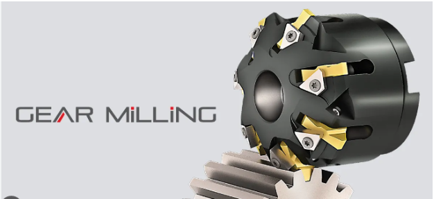
While hobbing uses a rotating, multi-edge tool in a coordinated generating process, gear milling cutters remove material to create gear tooth spaces through milling operations.
Depending on the cutter design and machining setup, gear milling can be useful for producing particular gear profiles, manufacturing specialized components, or handling production requirements that suit a milling-based approach.
Gear milling cutters are available in different designs to accommodate different tooth forms and machining needs. The correct choice depends on the geometry being produced and the machine’s capabilities.
How Does Gear Milling Work?
In a conventional form-milling operation, a cutter with a suitable profile removes material from the workpiece to create a tooth space. The workpiece is positioned, the cut is performed, and the component is indexed to prepare for the next space.
The cutter profile, indexing accuracy, workholding, and machine setup all influence the final geometry.
Unlike a generating process that develops the tooth form through coordinated motion, form milling relies more directly on the cutter’s profile. This distinction is important when deciding whether milling is the appropriate production method.
Not every gear milling operation follows the same sequence, and specialized equipment or alternative milling strategies may be used for particular component designs.
When Can a Gear Milling Cutter Be the Right Choice?
Gear milling cutters may be appropriate when the part geometry, production volume, machine availability, or manufacturing workflow favors milling.
Potential applications include:
- Specialized gear components requiring a particular tooth form
- Prototype and development work
- Selected low-volume production requirements
- Maintenance or replacement-part manufacturing
- Components that can be produced efficiently using an available milling setup
These are general application examples rather than universal rules. A high-volume operation may still benefit from milling in certain circumstances, while a small production run may be better suited to another process. The decision should be based on the actual component and production requirements.
What Influences Milling Accuracy?
A gear milling cutter cannot compensate for an inaccurate setup. Workpiece positioning, cutter condition, machine rigidity, indexing, and cutting parameters all contribute to the outcome.
Tool wear is particularly important. A worn or damaged cutting edge may affect tooth dimensions and surface quality, while incorrect indexing can produce inconsistent spacing between teeth.
Manufacturers should establish inspection procedures that verify the finished gear against its engineering drawing. Depending on the application, this may include checks of tooth thickness, spacing, profile, and other specified characteristics.
Worm Gear Hobs vs. Gear Milling Cutters: What Is the Difference?
Both tools remove material to produce gear-related geometry, but their operating principles and typical applications differ.
| Consideration | Worm Gear Hobs | Gear Milling Cutters |
| Basic approach | Hobbing uses coordinated tool and workpiece motion to generate tooth spaces | Milling removes material using a cutter in a defined machining setup |
| Tool design | Cylindrical, multi-edge hob designed for the intended geometry | Cutter profile and design selected for the required tooth form |
| Process considerations | Synchronization, hob geometry, machine capability, and setup | Cutter profile, indexing, workholding, and machine capability |
| Production suitability | Depends on the worm gearing design and hobbing setup | Depends on the gear geometry, milling method, and production requirements |
| Key selection factor | Compatibility with the intended worm gear geometry | Compatibility with the required tooth profile and milling process |
The central question is not which tool is universally better. It is which process can produce the required component accurately, consistently, and economically.
Five Factors to Consider Before Selecting Gear-Cutting Tooling
For U.S. manufacturers evaluating tooling options, a structured selection process can prevent avoidable machining problems.
- Start With the Engineering Drawing
Review the component drawing before discussing tooling. Identify the required gear type, tooth geometry, dimensions, tolerances, and any specified surface or inspection requirements.
The more clearly these requirements are defined, the easier it becomes to determine which cutting approach is suitable.
- Consider the Workpiece Material
Different materials respond differently to machining. Material hardness, strength, machinability, and heat-treatment condition can influence cutting forces, tool wear, and the choice of machining parameters.
A tool suitable for one material may not deliver the same performance with another. Material information should therefore be part of the initial tooling discussion.
- Match the Tool to the Machine
Machine compatibility is essential. The available machine must support the required tool, workpiece dimensions, cutting movements, and setup.
For hobbing, manufacturers should verify the necessary synchronization and machine capabilities. For milling, they should evaluate indexing, workholding, cutter mounting, and the ability to achieve the required tooth geometry.
- Balance Production Volume and Quality
Production volume can influence the preferred manufacturing process. A process that works well for a small batch may not offer the same economics for a large recurring order.
Compare setup time, cycle time, tooling costs, inspection requirements, and expected tool life. Evaluate these factors alongside quality requirements rather than considering purchase price alone.
- Plan for Inspection and Tool Maintenance
Tool selection is only the beginning. Regular inspection can help identify wear before it leads to unacceptable parts.
Manufacturers should define appropriate tool-condition checks, replacement criteria, and finished-part inspection procedures. Maintaining consistent setup practices also helps reduce variation between production runs.
Common Mistakes That Can Affect Gear Quality
Even a suitable cutting tool can produce inconsistent results when the broader machining process is poorly controlled.
Watch for these common issues:
- Choosing tooling before confirming the geometry: The tool must match the actual design, not just a general gear category.
- Ignoring machine limitations: Insufficient rigidity or unsuitable machine capabilities can undermine accuracy.
- Using worn tooling for too long: Excessive wear can affect dimensional consistency and surface finish.
- Overlooking workholding and alignment: Poor positioning can introduce errors even when the cutter is appropriate.
- Skipping process verification: Inspection is necessary to confirm that the finished component meets its specified requirements.
Addressing these factors early can help reduce rework, improve process consistency, and make production planning more predictable.
Building a More Reliable Gear-Manufacturing Process
Modern gear production depends on the relationship between tooling, machine capability, material selection, process control, and inspection. Worm gear hobs and gear milling cutters each have a role, but their value depends on how well they match the manufacturing objective.
For manufacturers across the USA, the most effective approach begins with a clear understanding of the component and ends with verified results. When tooling decisions are based on engineering requirements rather than assumptions, manufacturers are better positioned to maintain quality while managing production costs.
Explore Gear-Cutting Tooling With SS Tools
Selecting suitable gear-cutting tooling begins with understanding the component, its required geometry, and the machining process available to produce it.
SS Tools is a relevant starting point for manufacturers exploring gear-tooling requirements. Before making a selection, prepare the component drawing, workpiece material details, machine information, and required tolerances so that the tooling discussion can focus on the actual application.